Tip
This integration is specifically for German users under the rules of EnWG Paragraph 14a, which allows grid operators to temporarily limit power consumption of controllable loads during peak periods.
This guide will help you configure your SmartgridOne Controller to integrate with the SmartMeterGateway (SMGW) for Paragraph 14a compliance in Germany.
Supported Devices
| Device Type | Variants | Supported |
|---|---|---|
| Storage Devices | Charging Only | ⚠️ |
| EV Chargers | All | ✅ |
| Heatpumps | ||
| Cooling Devices | ❌ |
What you need
- SmartgridOne Controller with internet connectivity.
- Connection to a SmartMeterGateway (SMGW) with digital output signals.
- For standard controllers:
- Direct connection from the SMGW to the Digital Input (DI) pins on your controller.
- For lite controllers or controllers without DI pins:
- SG-ready relay module (DS1242)
- Ethernet connection from the controller to the relay module
- Connection from the SMGW to the DI pins on the relay module
How it works
The Paragraph 14a integration enables your system to respond to grid management signals from your distribution system operator (DSO). When the grid is under strain, your SmartMeterGateway will send a signal to your SmartgridOne Controller, which will temporarily limit the power consumption of connected devices to 4.2kW by default.
Configuration Process
The setup consists of two main parts:
- Adding the Digital Input Device
- Configuring the Paragraph 14a external signal
Part 1: Add the Digital Input Device
-
Log in to the commissioning interface.
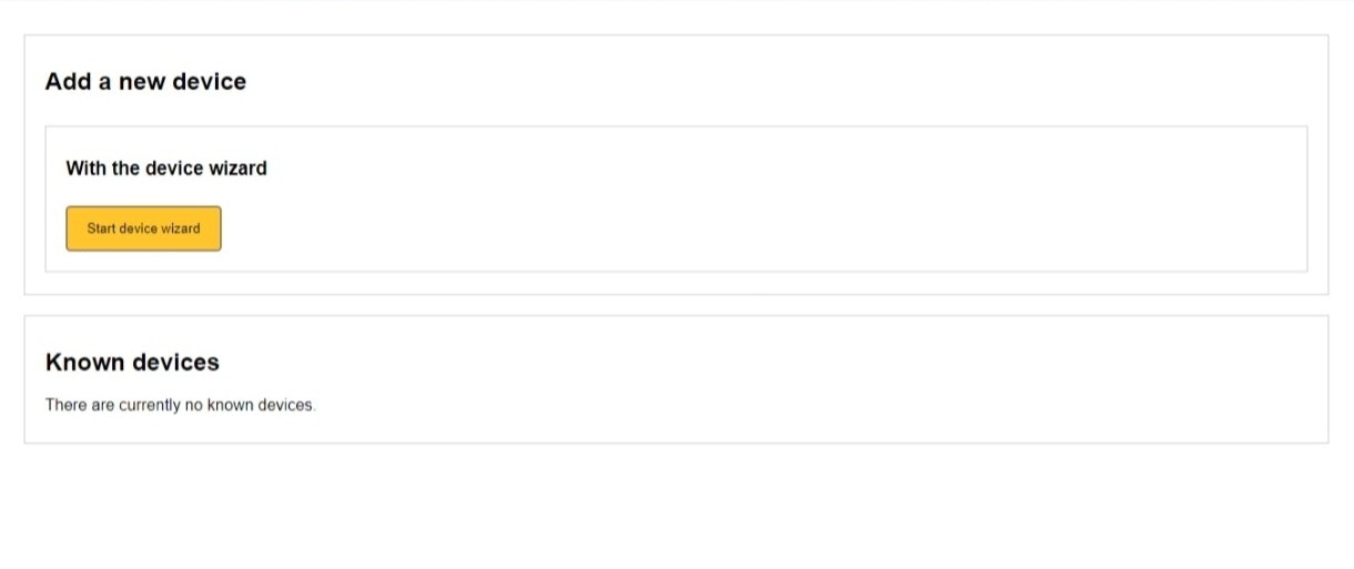
-
Go to the "Devices" tab and click "Start device wizard".
-
Based on your controller type, follow one of these paths:
For Standard Controllers:
- Choose "Energy Meter" as the device type
- Select "Generic" as the brand
- Select "Relay" as the connection type
- Select "Digital Input Device" as the model
For Lite Controllers:
- Choose "Energy Meter" as the device type
- Select "Generic" as the brand
- Select "Ethernet TCP to relay converter" as the connection type
- Select "DS1242" as the model
-
Complete the device wizard by following the on-screen prompts:
- Enter any requested additional inputs
- For Ethernet connections, select the device by MAC address (recommended) or IP address
- Adjust scan parameters if needed (default values are typically fine)
- Wait for the device to be found and save it
For detailed instructions on adding a device, see our Adding a Device guide.
Part 2: Add the External Signal for Paragraph 14a
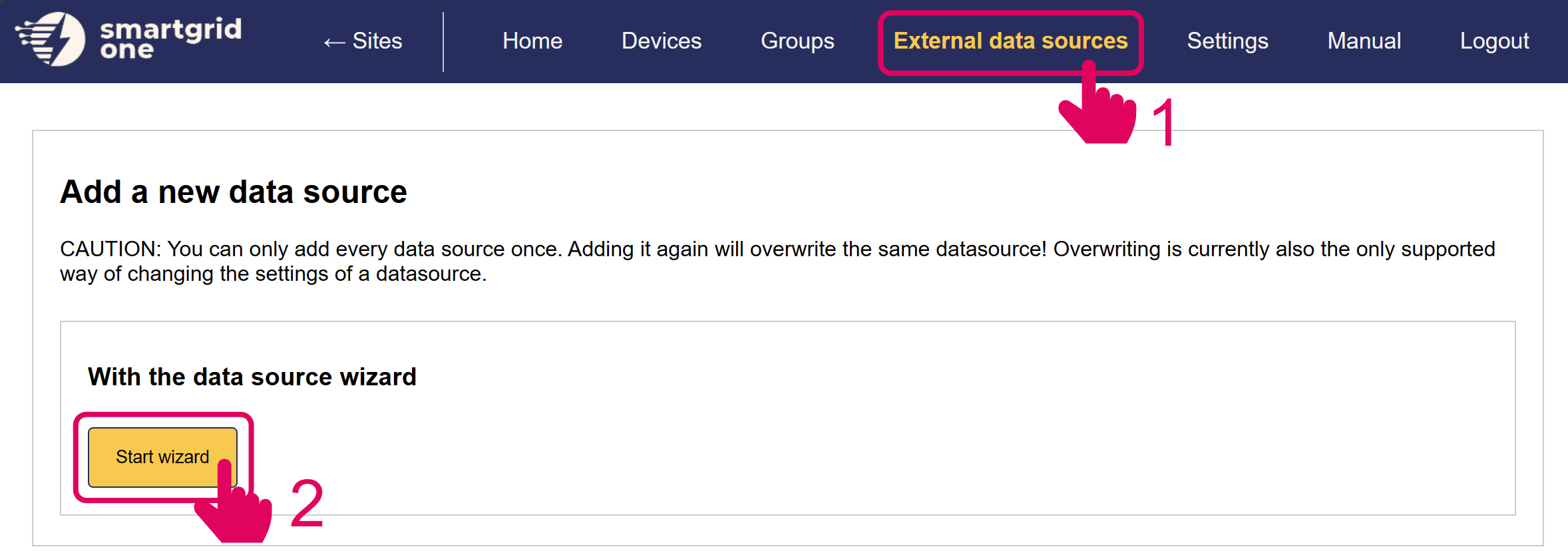
- Go to the "External Data Sources" tab and click "Start Wizard".
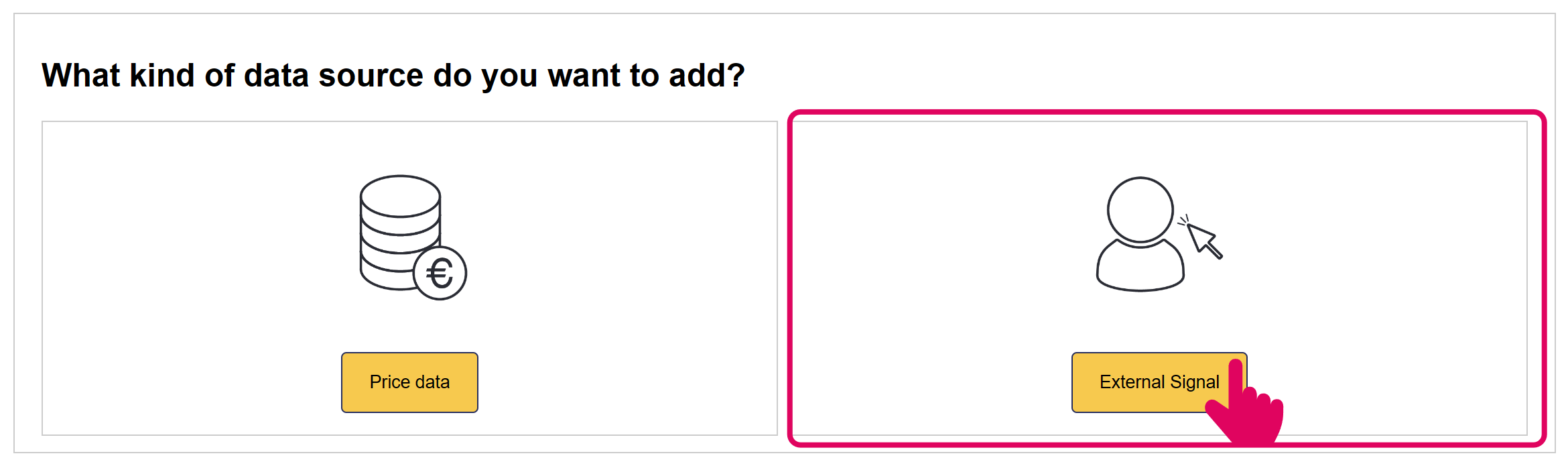
- Select "External Signal" as the kind of data source.
-
Navigate to and select "Paragraph 14a" from the available external signals.
-
Configure the Paragraph 14a integration:
- Choose all devices for which this signal should apply
- The default power limit is set to 4.2kW, which is the standard for Paragraph 14a compliance
- You can adjust this value if your agreement with the grid operator specifies a different limit
-
Complete the wizard by clicking "Save" or "Finish".
-
You should now see the Paragraph 14a signal added to your external signals list.
Technical Details
The §14a formula is used to calculate the allowed grid import limit for all controllable devices. The limit differs based on the number of devices, and it can be affected by total nominal power per device type.
When a §14a signal is received:
- The SmartgridOne Controller immediately limits the power consumption of selected devices
- The §14a limit applies at the grid connection point.
- Essential services remain unaffected:
- Household / non-controllable loads are not part of the §14a restriction.
- PV production and battery discharge may still be used behind the meter.
- Battery discharging is not restricted by the §14a grid-import limit.
- Normal operation resumes automatically when the signal ends
Warning
External Signal Priority The §14a signal has priority over local control modes and external signals. When active, it will limit power to controllables and then the local moode will have effect.
Direct Control
Direct control is not implemented, as this allows the grid operator to send device-specific setpoints (or limits). This does not require the use of an EMS.
EMS Control
EMS Control is enforced by calculating the consumption limit for all controllable devices on each individual location. The overall limit is dependent on the type an number of devices behind the grid meter.
The following formula is used to determine the limit per site:
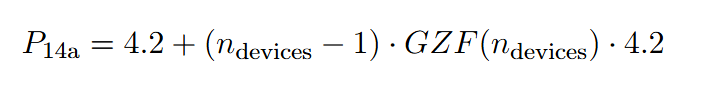
If the sum of the grid connection power of heatpumps or coolers is larger than 11kW, we use the following formula:

The number of devices is counted as follows:
- Batteries are counted individually.
- EVs are counted individually.
- Devices with a connection capacity lower than 4.2kW are not included
- Only heatpumps with a connection capacity lower than 4.2kW are included, if the overall connection capacity for all heatpumps is larger than 4.2kW. Then, we count all heatpumps as one device.
The simultaneity factor is determined using the following table.
| Number of Devices | GZF |
|---|---|
| 1 | 1 |
| 2 | 0.8 |
| 3 | 0.75 |
| 4 | 0.7 |
| 5 | 0.65 |
| 6 | 0.6 |
| 7 | 0.55 |
| 8 | 0.5 |
| 9+ | 0.45 |
In addition to the controllable consumption limit, the following formula is used to set the overall grid limit, to compensate for production power:

Use Cases
Case 1.1
-
An installation with five heatpumps of 2kW each is activated, and three batteries of 2kW.
- If the batteries are charging:
- The heatpump consumption limit is 4.2kW.
- If the batteries are discharging:
- The heatpump consumption limit from the grid is 4.2kW. The battery power can be used for the heatpumps, increasing their consumption limit to the maximum of 10kW.
- The batteries are ignored because their connection capacity is smaller than 4.2kW each.
- If the batteries are charging:
Case 1.2
-
An installation with five heatpumps of 3kW each, an EV charger of 10kW and a battery of 7kW is activated.
- If the battery is charging:
- The controllable consumption limit from the grid is 12.3kW (6kW for the heatpumps, and 6.3kW for the EV and battery).
- If the battery is discharging:
- The controllable consumption limit from the grid is 12.3kW. The overall consumption limit can be increased to 19.3kW by the discharging battery.
- If the battery is charging:
Case 1.3
-
An installation with five heatpumps of 3kW each is activated, and PV is producing 2kW.
-
The controllable consumption limit is 8kW, and the net limit is 6kW.
Case 1.4
-
An installation with five heatpumps of 3kW each is activated, there is 4kW uncontrollable load and PV is producing 2kW.
-
The controllable consumption limit is 6kW, and the net limit is 8kW.
Case 1.5
-
An installation with five heatpumps of 3kW each is activated, there is 2kW uncontrollable load and PV is producing 4kW.
-
The controllable consumption limit is 8kW, and the net limit is 4kW (we are taking 6kW from the grid for controllable loads and injecting 2kW).